
The schematic revealed that the Crosley 52 is a basic regenerative receiver. The first tube does all the RF work. The second and third tubes are for audio amplification only.
https://www.radiomuseum.org/r/crosley_52.html
The grid leak resistor was also found to be open-circuit. It is supposed to be 3 megaohm, so hiding a modern resistor under the grid leak resistor holder, was easily done to maintain proper operation.

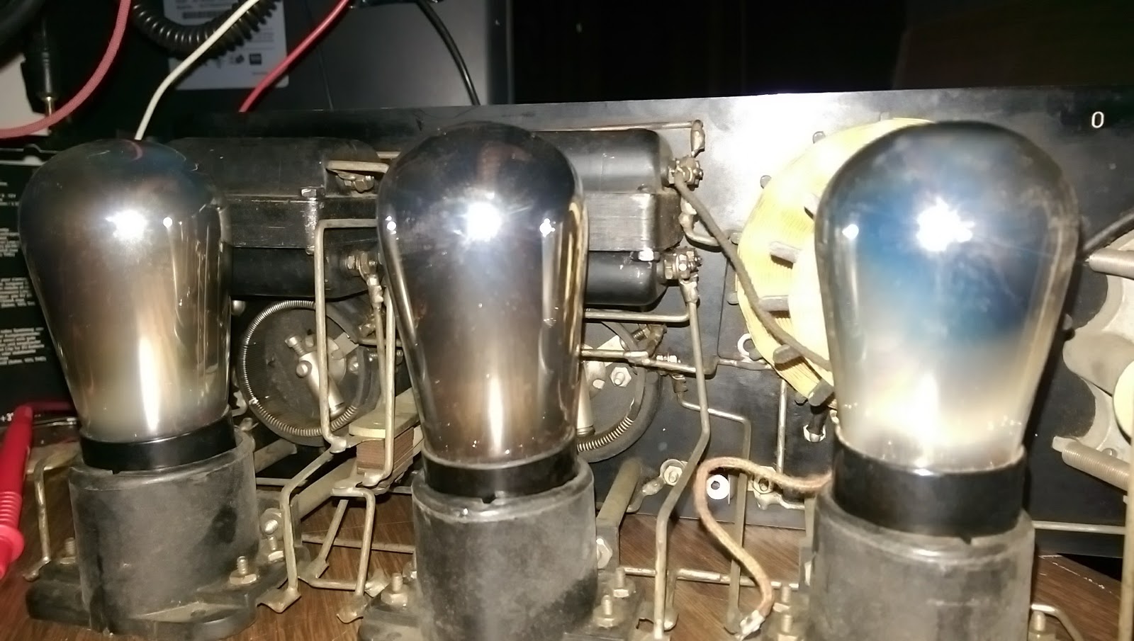
The chassis is held rigid by the thick wiring to the tube sockets. The cloth-covered wire of the tickler coil is all intact.

After the dirt was cleaned away from the chassis, and the tube sockets cleaned, all the filaments did not glow. I had to solder a short between two of the windings on the filament rheostat.

All the wiring was intact. This radio was probably forgotten on a shelf somewhere for many years and not abused. The front of the radio was easily cleaned from years of dirt.

Replacement of the power switch was going to be a difficult matter. The switch operates by pulling the stem out. I found a piece of brass rod, put it in the lathe and turned it down. A plastic sleeve fits over the stem, and a steel ring makes the contact. The rear of the stem is drilled and tapped for a screw, which holds on a washer keeping the whole assembly from popping out of the front. Only an expert is going to spot that it isn't original. The point is that it works and I haven't done any modification that isn't reversible if I do locate an original switch assembly.

This radio was intended to run from batteries, but since Burgess has long been out of business, there's no ready source of period-correct batteries. I want to run it off the mains anyway, so I need to build a power supply. The power supply has to produce +5vdc for the filaments and +45vdc and +22vdc for the tubes. Normally this would be done with 4 No. 6 dry cells and a B+ battery like the 10308. I felt that No. 6 dry cells were pretty big, so I started looking for alternatives like a 2FBP dry cell. Searching the internet for resources led to a page to which someone has kindly scanned in a set of battery boxes from these old dry cells. BINGO! However the scans weren't good enough quality to simply print out. I spent basically a whole day re-creating the artwork for these Burgess dry cells in Inkscape vector drawing software. The results a reasonably good. The cells look good sitting on the shelf next to the Crosley radio.

Arts and Crafts

Filling the mockup dry cell with a block of wood and instant concrete yields a reasonable weight.

All that was missing was a speaker. There were plenty of Atwater-Kent speakers to choose from, but I felt that a reasonable Crosley speaker would be the only acceptable solution. The swap meets didn't yield any results, so on ebay I was able to find a good working example of a Dynacone Type F. This has a field coil that can be powered up by the A+ supply. I wasn't able to get exact specs, so using only 5 volts with a 500 ohm coil seemed a good limitation. If someone can find better ratings for this field coil, I would be happy to know. I tested the speaker using a LM385 amplifer driving into an impedance matching transformer. It worked, but sounded terribly over-driven. I hoped that driving it from a tube would yield better results. Otherwise it would mean tearing the speaker down for an overhaul.

The audio wasn't particularly strong, and I believe the power supply needs a larger filter capacitor to clean up the hum.
With the radio chassis sorted, the battery eliminator case needed designed. This housing was to be a Burgess 10308 B+ battery. This battery is quite large and will easily house the entire power supply. An additional connector will be used for the filament voltage and hidden out of view near the 120vac cord. I decided to make the box out of acrylic glass and finally adhere the artwork to it when everything is finished. The scanned artwork wasn't clear enough for my liking, so I re-drew the whole thing in Inkscape for a crisp clear final product.

Attaching the artwork was done with some 3M "Super 77" spray contact cement. The acrylic glass was first scuffed with a Scotchbrite pad so the adhesive would stick better. The result is a nice battery box.

"Recognized by their stripes; Remembered by their service."
The circuit board and transformer was affixed to a wooden block. The rear of the box has to allow the cord to leave through a hole in the bottom, and I decided to put a lighted power switch in it.


The fahnestock clips were installed and another test was done to insure all was right.

All was not right, however, and the speaker had to be stripped down for some adjustment and cleaning. I ended up taking the whole thing apart and cleaning it out. The adjustment screw needed lubricated anyway. After that was done the volume could be adjusted much louder.

The whole setup was moved to the shack and re-assembled on a shelf for display and use. I need to obtain some cloth-covered wire for aesthetics. That concludes the overhaul and restoration of this fine surviving specimen.
No comments:
Post a Comment