The subject this morning is a USB to CAT CI-V interface cable. Someone (not me) plugged it into the wrong 3.5mm port and blew the chip up so badly that the case was deformed due to the heat. The chip was obviously bad, there are very few other chips on the board, so I just ordered a new chip.
Some folks don't have a hot-air desoldering tool for surface mount components. So how does your average Plugger of ham get a multi-pin surface mount chip off the board without damaging the board? When you know you have a ready replacement chip there's an easy way to remove it from the board. Don't try to unsolder every lead and try to preserve the chip. You will get frustrated. Just clip the leads off with your best fine clipping tool or EXACTO knife. Tip the chip up and clip the remaining leads.
I have a simple general use soldering iron as well, it gets a LOT of use. I don't file my tip down. I take it out anneal it in a and hammer it down to a fine point on the anvil. The act of hammering it to a point makes the tip hard again. I find it lasts a lot longer this way. You will need a sharp tip on your iron to do this properly.
This is what makes it easy, just take the hot soldering tip and wipe it across the lands of the board. The clipped off leads will stick to the iron and they will just be left behind when you dip the iron's tip in the cleaning sponge. Easy!
Once the chip is off then using a set of helping hands and magnifying glass, putting the new chip in place is simple (provided your hands are steady and your eyesight is good). The lands should be clean and only a tiny amount of solder is required to make the connection.
None of us are getting any younger, so using a eye loop and a magnifying glass in conjunction can be helpful too. Hope you find these tech tips helpful. de N3FIX at the Cly Institute for Radio Repair.
Some older transceivers don't have a separate Receive Antenna Input jack. A Receive Antenna can be a beverage, e-field probe, or other active antenna. The advantages of using one antenna with lower noise on receive and a tuned antenna on transmit are obvious.
Since my IC-746 does not have this feature, I needed to construct a simple relay box. The box would have three coax connectors, a connection to the rig for the send and power, and also a power output to source my active antenna.
The theory of operation is one that takes into account the safety of the transceiver and the active antenna. The failsafe state is TX antenna position. If the circuit fails to power up (or the fuse blows), the TX antenna will stay in circuit. Likewise, if the circuit fails to power up, the active antenna will not get any power. Only when the rig powers the relays will the active antenna attached to RX be connected and powered up. The HSEND output from the radio likewise provides a safety. It disengages the RX active antenna power through the Rp relay, and then subsequently drops out the Rt relay so that the rig may transmit into the TX antenna.
Here are all the parts on the table ready to assemble. I chose an aluminum 6x4x3 BUD box since aluminum is much easier to work with. I also have two 12 volt relays, one small one to switch the loads and one large one to switch the RF. I kept the RF leads as short as possible, and also used shielded cable between the radio and the relay box.
The coax connectors were placed at a certain height so the relay would be very close to them. Keep in mind that the general purpose relay that was employed in this project is not going to be good for anything above HF frequencies. If I could have sourced an economical coaxial relay, that would have been better. This would not work very well as a relay box for using your SDR as an separate RX radio. (That may be a project for the future.)
The fuse protects the rig's ACC2 jack from excessive current draw. The switch disables the operation of the relay box if the receive antenna is not desired. The indicator illuminates when the RX antenna is in circuit and powered up. The lamp goes out when the rig goes into transmit.
The wiring was done point-to-point to keep the leads short. The control and power cable goes out the back bottom of the enclosure through rubber grommets.
The result is good. The relay switches between RX and TX antenna when the rig is keyed and the switch is up. When the switch is left down (in bypass), the RX antenna is not connected at all and all signals go through the TX antenna.
The final touch was to put some magnetic feet on it, so it sticks to the top of the radio. Then apply the labels.
Welcome back to the Cly Institute for Radio Repair subsidiary of the Imp Barn. The institute wants to be capable on as many bands as we are licensed to operate on.
The WARC bands are three portions of the shortwave radio spectrum consisting of 30 meters (10.100–10.150 MHz), 17 meters (18.068–18.168 MHz) and 12 meters (24.890–24.990 MHz). They were named after the World Administrative Radio Conference, which in 1979 created a worldwide allocation of these bands for amateur use. The bands were opened for use in the early 1980s. They can sometimes be ignored by ham operators, but possess good opportunity for DX under the right conditions. My manual tuner works HARD to make my transceiver happy on these bands with my existing equipment for very poor efficiency, and very few contacts.
In researching the availability of antennas for these bands I found very little. Verticals are available from the usual sources, but the cost is prohibitive. (I didn't want to include 60m in this design either since my radio doesn't do 60.) The bands are nice and narrow bandwidth with little need to strive for obtaining wide bandwidth capability in a design. I normally run a commercial "fan" dipole which Alpha-Delta refers to as a "parallel" dipole for 80, 40, 20, 15, and 10 meters. What was needed was a simple wire solution. I was inspired by an article by W4DAN for this fan dipole design. The solution was simple, create a fan dipole for the WARC bands using first principles where the calculation is 468 / freq in Mhz = total length in feet for a half wave dipole.
To reduce interactions between elements, I spaced them 6 inches apart. This may be excessive, but works fine. The center is an old 1:1: balun I found at a hamfest.
With the longest element of just over 23 feet in the center, the next longest on top and the shortest on the bottom. A Dacron rope makes up the difference between the 17m and 12m element to reach the last spacer.
30m just over 23 ft
17m just under 13 ft
12m just over 9.5 ft
Here's a shot at dusk before the tuning process got fully underway. We did all this work by flashlight in the dark. This has few advantages, but at least the neighbors don't stare. Its SCIENCE folks!
When tuning this antenna, I put the center up on a thin bamboo pole supported by my son's wooden swing set, and supported either end so that I could reach up at the end and grab it. After getting the wire in hand I could walk hand-over-hand bending the bamboo pole down to reach the end of the element for tuning. This was rather more like an Inverted-Vee arrangement which will result in slightly shorter lengths and will be ideal for mounting where there are no high objects to tie to. At the recommendations of my elmers, I started with the 30m elements and tuned them to under 1.5:1 SWR. Progression was to adjust 17m and then 12m elements. I noticed little interaction between those elements while tuning. I did jump back and forth once between 17m and 12m to get the tune just right. The bamboo pole worked well for a temporary tuning setup. A final mounting location is yet to be determined.
Using my VK5JST analyzer, we were able to get the tuning reasonably close. I discovered that a simple technique to keep me from cutting too much off the elements. It didn't seem to affect the tuning and I would encourage others to take advantage of this trick to enable you to re-tune an antenna in its final installation for perfect matching.
I folded the element back on itself and used a cable clamp to secure it. The loop can be adjusted easily by loosening the cable clamp and re-tightening. The element wire in the loop didn't seem to matter much, but I kept it to a minimum without too much wire involved in the loop simply for fine tuning.
Good high quality T-B ty-wraps were used to keep the spreading spacers taut with the 30m elements, and with the spreader near the feed point to keep everything aligned. The ty-wraps can be adjusted slightly if needed but provide a good solid way of keeping the spreaders in place. This is what Alpha-Delta uses, so why not!
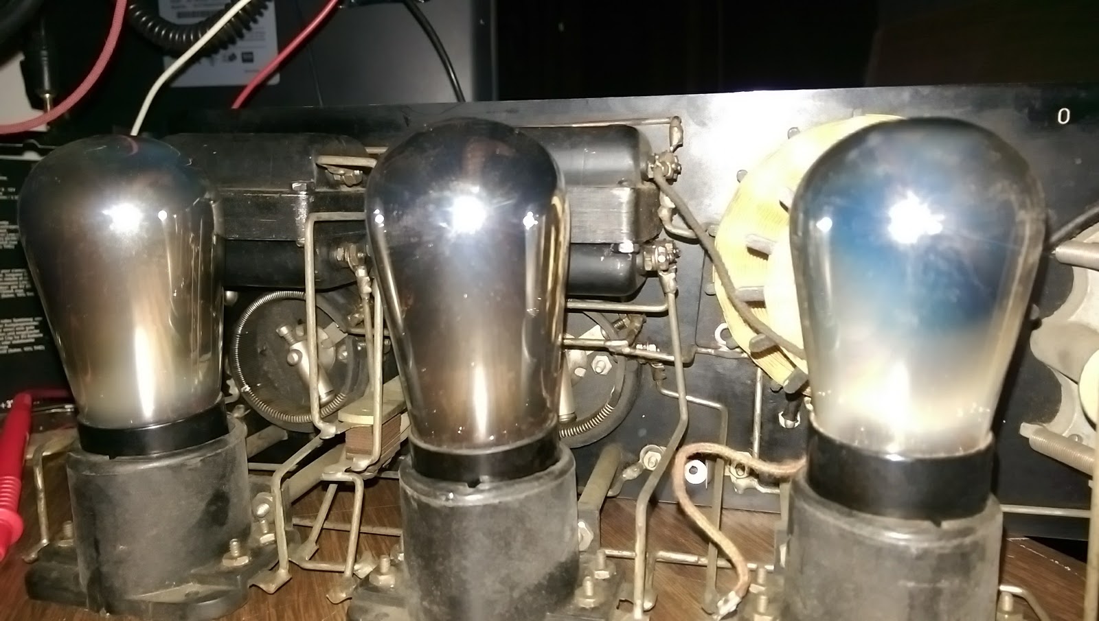
This beauty was found at our club swapmeet. It is a nearly complete radio. The power switch was missing along with a few of the knurled screws. The case is in nice shape too. I brought it home for nearly market value and discovered that the tubes were also good.
The schematic revealed that the Crosley 52 is a basic regenerative receiver. The first tube does all the RF work. The second and third tubes are for audio amplification only. https://www.radiomuseum.org/r/crosley_52.html
The grid leak resistor was also found to be open-circuit. It is supposed to be 3 megaohm, so hiding a modern resistor under the grid leak resistor holder, was easily done to maintain proper operation.
The chassis is held rigid by the thick wiring to the tube sockets. The cloth-covered wire of the tickler coil is all intact.
After the dirt was cleaned away from the chassis, and the tube sockets cleaned, all the filaments did not glow. I had to solder a short between two of the windings on the filament rheostat.
All the wiring was intact. This radio was probably forgotten on a shelf somewhere for many years and not abused. The front of the radio was easily cleaned from years of dirt.
Replacement of the power switch was going to be a difficult matter. The switch operates by pulling the stem out. I found a piece of brass rod, put it in the lathe and turned it down. A plastic sleeve fits over the stem, and a steel ring makes the contact. The rear of the stem is drilled and tapped for a screw, which holds on a washer keeping the whole assembly from popping out of the front. Only an expert is going to spot that it isn't original. The point is that it works and I haven't done any modification that isn't reversible if I do locate an original switch assembly.
This radio was intended to run from batteries, but since Burgess has long been out of business, there's no ready source of period-correct batteries. I want to run it off the mains anyway, so I need to build a power supply. The power supply has to produce +5vdc for the filaments and +45vdc and +22vdc for the tubes. Normally this would be done with 4 No. 6 dry cells and a B+ battery like the 10308. I felt that No. 6 dry cells were pretty big, so I started looking for alternatives like a 2FBP dry cell. Searching the internet for resources led to a page to which someone has kindly scanned in a set of battery boxes from these old dry cells. BINGO! However the scans weren't good enough quality to simply print out. I spent basically a whole day re-creating the artwork for these Burgess dry cells in Inkscape vector drawing software. The results a reasonably good. The cells look good sitting on the shelf next to the Crosley radio.
Arts and Crafts
Filling the mockup dry cell with a block of wood and instant concrete yields a reasonable weight.
All that was missing was a speaker. There were plenty of Atwater-Kent speakers to choose from, but I felt that a reasonable Crosley speaker would be the only acceptable solution. The swap meets didn't yield any results, so on ebay I was able to find a good working example of a Dynacone Type F. This has a field coil that can be powered up by the A+ supply. I wasn't able to get exact specs, so using only 5 volts with a 500 ohm coil seemed a good limitation. If someone can find better ratings for this field coil, I would be happy to know. I tested the speaker using a LM385 amplifer driving into an impedance matching transformer. It worked, but sounded terribly over-driven. I hoped that driving it from a tube would yield better results. Otherwise it would mean tearing the speaker down for an overhaul.
The last step was to make a power supply battery eliminator. This will be built into a mockup 10308 Burgess battery. Testing the radio for the first time the power supply was just built as a breadboard circuit. The transformer puts out 190 volts center-tapped at 25 mA. Using 22 volt zener diodes each step of voltage is available to power this radio.
The audio wasn't particularly strong, and I believe the power supply needs a larger filter capacitor to clean up the hum.
With the radio chassis sorted, the battery eliminator case needed designed. This housing was to be a Burgess 10308 B+ battery. This battery is quite large and will easily house the entire power supply. An additional connector will be used for the filament voltage and hidden out of view near the 120vac cord. I decided to make the box out of acrylic glass and finally adhere the artwork to it when everything is finished. The scanned artwork wasn't clear enough for my liking, so I re-drew the whole thing in Inkscape for a crisp clear final product.
Attaching the artwork was done with some 3M "Super 77" spray contact cement. The acrylic glass was first scuffed with a Scotchbrite pad so the adhesive would stick better. The result is a nice battery box.
"Recognized by their stripes; Remembered by their service."
The circuit board and transformer was affixed to a wooden block. The rear of the box has to allow the cord to leave through a hole in the bottom, and I decided to put a lighted power switch in it.
The fahnestock clips were installed and another test was done to insure all was right.
All was not right, however, and the speaker had to be stripped down for some adjustment and cleaning. I ended up taking the whole thing apart and cleaning it out. The adjustment screw needed lubricated anyway. After that was done the volume could be adjusted much louder.
The whole setup was moved to the shack and re-assembled on a shelf for display and use. I need to obtain some cloth-covered wire for aesthetics. That concludes the overhaul and restoration of this fine surviving specimen.
The Icom IC-207H is a nice radio. I was fortunate enough to obtain one from a friend. It was used hard and its beginning to show. However, as a mobile rig goes, its a small tough package. The problem is that I've begun receiving reports that my signal is breaking up when the radio gets hot.
A fellow ham also has a IC-207H and recommended to inspect the SC-1091 VHF power module. Apparently this module has a ceramic substrate and will form cracks due to uneven heating. He recommended bridging the cracks with solder and a thin wire.
Since the IC-207H dual band mobile is a fairly simple rig, disassembly is easy. First remove the head unit and the screws that hold the head connector on the main unit. Remove the four bottom case screws and then remove all the screws from the main board and the two retaining screws from the power modules. Unsolder the antenna connector and slip the board out.
The 2 meter power module is the one with fewer wires coming out of it. (The 70cm module is actually sealed and you can't get into it anyway.) Unsolder the 2 meter power module and GENTLY pry the black cover off. Its on there pretty good, so just work it off a little at a time. Don't break the ceramic substrate. Once the cover is off inspect the ceramic for hairline cracks. Use a soldering iron with HIGH heat >40w and bridge any gaps in the traces with some light wire and good solder. The module dissipates heat quickly, don't use too much solder or you'll just have a blob.
You can see the hairline crack on this module and then how it was repaired. You have to look really hard to see the crack. Its in the center of the board.
Forgive the globbly solder, its on there good, but its hard to get it hot enough to melt uniformly. I didn't want to make it worse by overheating the ceramic in one spot with the soldering iron.
When re-assembling grind the little clip areas off the inside of the 2 meter power module cover. This will reduce the stress on the ceramic during re-assembly. After this repair procedure the radio works great.
There is some documentation floating around concerning the failure with the Icom IC-746 and self oscillation on the 6 meter band. The suggestion is that the radio begins to receive itself through coupling of the open contacts of the TX/RX relay. When this happens the radio goes out of control, with all the meters going full scale. The power output is real, but there is no audio. It started during the January VHF contest and got consistently worse.
I replaced Q25 and D22, but that didn't solve the problem. I also saw that my radio had the factory mod for the PIN diodes around IC151. They were found to be ok, but replaced anyway.
The concept of the "crowbar" relay to ground the RX line during transmit seemed the right thing to do. There was also plenty of space to install the relay. I chose a very small 12v relay that could mount right above the L28 inductor. I removed some of the green surface of the ground plane of the board with a diamond bit engraving tool to expose pure copper of the board. This allowed me to solder the relay's contact leads directly to the surface of the board. The other side of the NO contact went to the trace that joined L28.
The coil wires of the Crowbar relay were run external to the board over the edge and to the same points as RL4.
The installation is clean and the radio works great now! Full power restored to 6 meter band and the autotuner now works again.
Control Board from the bottom showing the Crowbar relay coil wires.
Postlogue:
The crowbar modification was working well for almost 10 months. Then something in the setup changed which stopped it from working. The Receive Antenna Relay Box modification plugged into the ACC2 port seems to draw enough current from the trigger line that it stops the crowbar relay from working. When the plug was removed from the ACC2 port, the crowbar relay started working again. Make sure the main power supply voltage is at specification as not to produce a brown-out condition on these modifications.